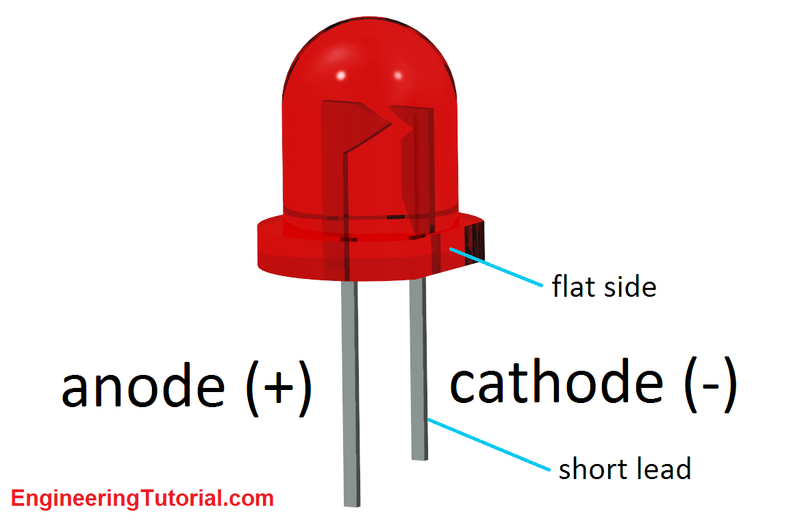
Wunderschöne Led Schematic Symbol Polarity Bilder. Now, your circuit is complete, and we have duplicated the circuit that is shown in the starter kit schematics, but we need to change the software. The led has a polarity that is shown in the following figure. There are a handful of identifiers for sometimes it's easiest to just use a multimeter to test for polarity.
American national standards institute (ansi) and the international electrotechnical commission (iec).
An electronic symbol is a pictogram used to represent various electrical and electronic devices or functions, such as wires, batteries, resistors, and transistors, in a schematic diagram of an electrical or electronic circuit. The symbols for different electronic devices are shown below. Start studying electronic schematic symbols. An overview of the most used schematic symbols in electronic circuits. Led pspice datasheet orcad schematic symbols library led led pspice model orcad pspice book transmission line model orcad pspice vip10 lmh6643 lmh6622 national semiconductor text: Maybe i'm having a little bit of a brain fart. Passive devices are devices that do not change or amplify voltage or current when another parameter is. Standard electrical iec symbols also known as iec 60617 (british standard bs 3939) used to represent various devices including pilot lights, relays, timers and switches for usage in electrical schematic diagrams. Should i take this to mean that there is a conventional orientation for the opening and hinge, so to speak, of the switch symbol in a schematic? I used a symbol of a diode in a box for the cells, which i assume is based off this model commonly used to and if i use the diode symbol, how is the polarity?