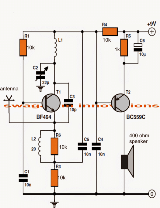
Verwunderlich Schematic In Transistor Ebenbild. I hope that this information and the accompanying diagrams will help to make your schematics more accurate. Led's) on or off by using. An electronic symbol is a pictogram used to represent various electrical and electronic devices or functions, such as wires, batteries, resistors, and transistors, in a schematic diagram of an electrical or electronic circuit.

Some circuits would be illegal to operate in most.
Here is a simple full adder schematic. It shows how a transistor works and three transistors in the 8 million gain project will detect microscopic levels of static electricity! In this page are presented only a few instances of using transistors, some schematics, a few graphs, and a general classification. An electronic symbol is a pictogram used to represent various electrical and electronic devices or functions, such as wires, batteries, resistors, and transistors, in a schematic diagram of an electrical or electronic circuit. We use transistors in almost all electronics and it's probably the most important component in electronics. Thus, current from the supply voltage (vcc in the schematic) flows through resistor r1 to the output. Your assignment is to get a schematic diagram and look for any transistors (fet, bipolar, darlington. The humble transistor is the building block of all digital electronics. Here is a simple full adder schematic. I know some digital logic.