Stilvolle Schematic Transistor Inverter Bild. Circuit inverter 12v to 220v 100w by transistor. The breadboard schematic of the circuit above is shown below. Originally i used a 555 timer and a cd4017 decade counter to produce the modified.
Circuit inverter 12v to 220v 100w by transistor.
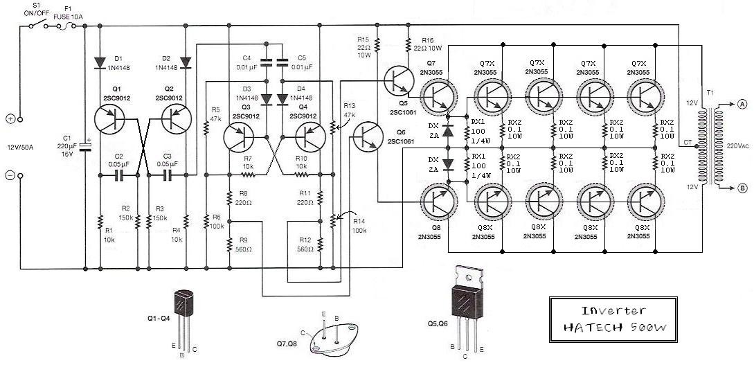
Advantages and disadvantages of this inverter. The transistors in the above circuit holds the most the frequency of the above pulse depends on the values of resistors and capacitor connected to it. These pulse trains are preamplified by the two tip122 transistors.the out puts of the tip 122 transistors are amplified by four 2n3055. The breadboard schematic of the circuit above is shown below. Originally i used a 555 timer and a cd4017 decade counter to produce the modified. So this is just a basic inverter circuit built using a mosfet transistor. Here is a simple but powerful, stable and efficient schematic diagram for a 500w modified sine wave inverter circuit. So you cannot use it for powering tv, laptops, monitors. Service manuals, schematics, eproms for electrical technicians. For info on inverter oscillators you can also refer to the complete tutorial which explains how to design an inverter from the scratch.